TurboRAN Hardware
General Hardware Design:
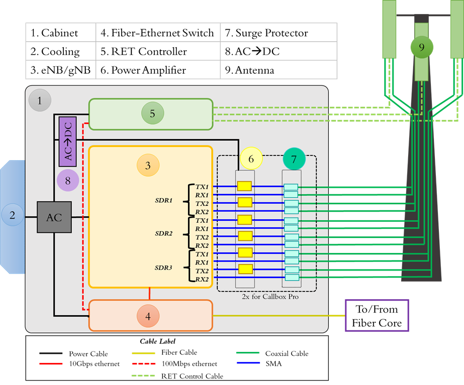
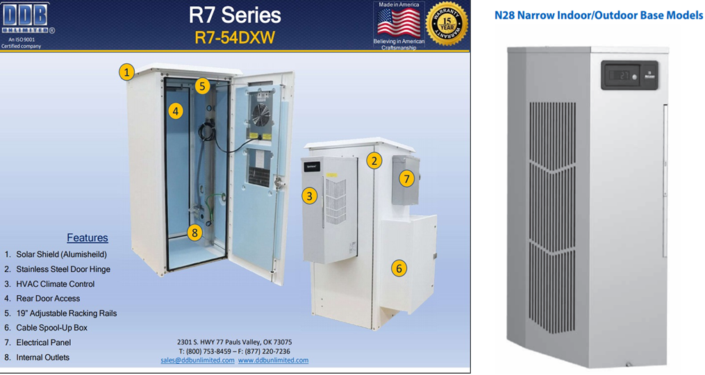
Figure. 1 shows the high-level block diagram used for TurboRAN deployment. This block diagram shows the main hardware components of TurboRAN including base stations, amplifiers, Remote Electrical Tilt (RET) controller, switch, cabin, cooling, and antenna system. Additionally, this block diagram shows the connection between the different components as well as the types of cables used in the deployment. The protective cabin shown in ① encloses the majority of the equipment. To maintain the temperature inside this cabinet, a cooling system shown as ② is used. Labeled ③ in the figure is the main equipment composed of SDRs and 3GPP compliant software to act as the base station. To connect it to the Internet and other base stations via fiber, a fiber-ethernet switch is exploited as shown in ④. The SDRs of the callbox are connected to the amplifiers using SMA cables. More specifically, the transmitter is connected to RF power amplifiers (PA) ⑥. Before terminating the coaxial cables to the antenna ⑨, a surge protector ⑧ is inserted to protect the base stations against lightning strikes. Finally, to regulate the tilt adjustment remotely, a RET controller ⑤ is attached to the antenna through a RET controller cable. Most of the components use an AC power supply except for the amplifiers which need DC. For amplifiers, TurboRAN uses AC to DC converter.
Base Stations:
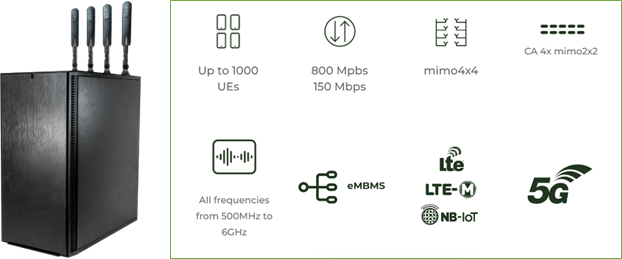
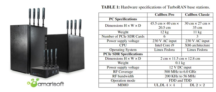
TurboRAN uses two different series of the Amarisot Callbox namely Amarisoft Callbox Pro and Callbox Classic shown in Figure 3. Table 1 summarizes the key features of Amarisoft Callbox Pro and Classic. Amarisoft Callbox works with a variety of networks, including 5G Standalone (SA), 5G Non-Standalone (NSA), LTE, and NB-IoT. The 4G and 5G implementations are compliant with 3GPP-release 14 and 15, respectively. In comparison to other alternatives, EPC implementation is combined with 3GPP-compliant 5GC. TurboRAN can support up to 6 SDRs for Amarisoft Callbox Pro and 3 SDRs for Amarisoft Callbox Classic. Each SDR card supports:
- RF coverage: 500 MHz to 6 GHz
- Bandwidth: 200 kHz to 56 MHz
- 2x2 MIMO (2 transmitting ports and 2 receiving ports)
- GPS connector to connect an external GPS clock
- Time Division Duplex (TDD) and Frequency Division Duplex (FDD)
- Maximum output power of 5 dBm (depending upon frequency)
- Maximum SDR input power -10 dBm
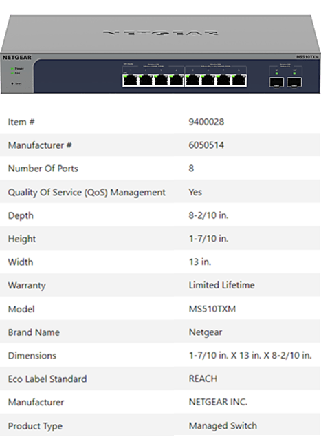
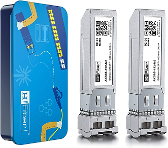
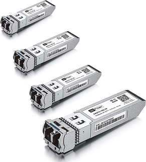
Fiber/Ethernet Switch:
For internet connectivity to the base stations, turboRAN uses Netgear ethernet switch shown in Figure. 4 combined with the multimode SFP and single mode SFPs shown in Figure. 5 and Figure. 6, respectively. Table in Figure. 4 shows the specifications of the Netgear switch.
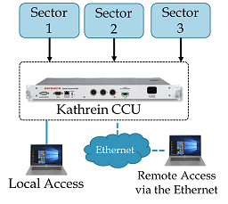
RET Controller:
Kathrien Central Control Unit (CCU) is used in TurboRAN for RET Controller. The CCU acts as an interface between the antennas’ remote-control unit (RCU) and the control system, and can be operated both locally and remotely. Figure. 7 shows the approach to connect CCU with antennas with a dedicated RET controller cable for each antenna.
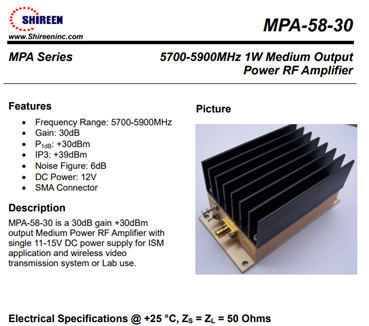
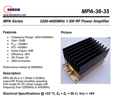
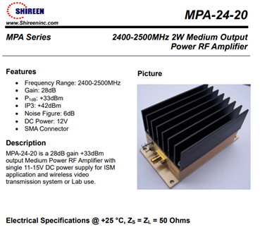
Power Amplifiers:
To support outdoor communication using TurboRAN, power amplifiers are connected in the transmit chain. Figures. 8, 9 and 10 show the specifications of power amplifiers used in turboRAN for successful outdoor transmission at three different frequency bands.
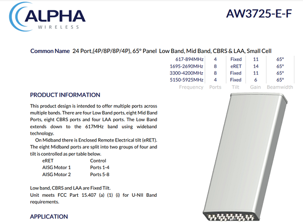
Antennas:
The specifications of outdoor antennas are shown in Figure. 11, operating on the same frequency bands as the available amplifiers on turboRAN. Furthermore, the antenna tilts at 2.4 GHz band is available and can be controlled through the RET controller.
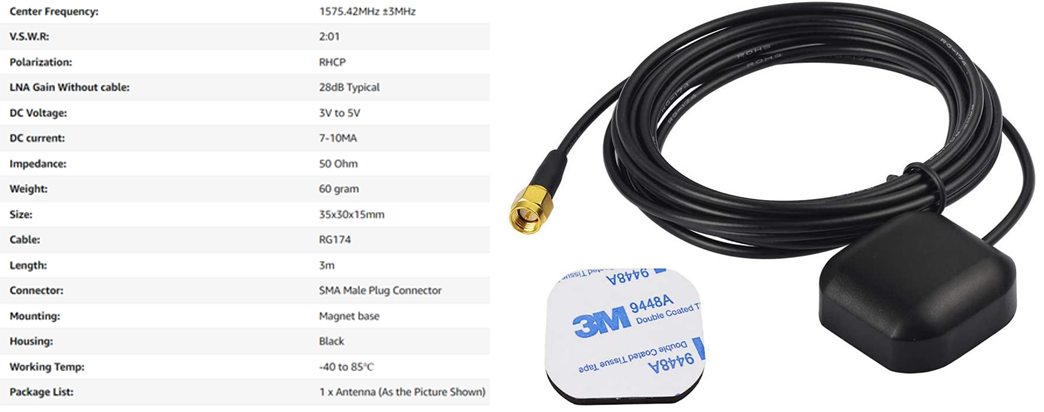
GPS for synchronization:
Each turboRAN site has GPS antennas shown in Figure. 12 for synchronization. The specifications of the antennas are given in the Table shown in Figure. 12.
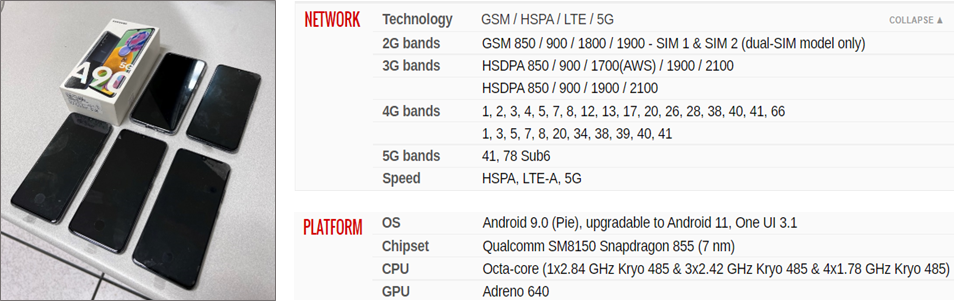
5G Phones:
For testing and data gathering, multiple Samsung Galaxy A90 5G-capable phone shown in Figure. 13 are also available in TurboRAN. Table in the Figure. 13 lists the technical specifications of the phones.
UE Simbox:
To simulate loaded base stations, multiple Amarisoft UE simboxes shown in Figure. 14 are also available in turboRAN. Each simbox can simulate upto 1000 UEs.